Showing posts with label ibm. Show all posts

Saturday, March 2, 2019

Oracle Licensing and Virtualization Restrictions

Disclaimer

The information here represents my personal findings using published documents from Oracle. It doesn't represent my legal opinion. I am not a lawyer. Take this information and fight for your right as a consumer/customer and demand an official response from Oracle by email, not verbal.

Introduction

I've had numerous encounters with customers citing Oracle sales people stating that virtualizing Oracle DB on VMware is not supported, and that the licensing of the entire physical host's cores, or even the entire cluster's cores is mandatory, and in a nut shell: this is NOT entirely true and can be circumvented.

The information below is based on Oracle's legal documents and licensing documents and guidelines. Check the references for the links and details.

References are denoted with numbers. When you see #1 it means see reference number 1 at the end of this post.

Executive Summary (TL;DR)

The Oracle partitioning guide is not a contractual document and Oracle strictly states it's for educational purposes only. Therefore it cannot use it to impose how customers should partition their environments or systems.

Excerpt from Oracle's "Oracle Partitioning Policy" document

Details and Resources

The only contractually obligating documents from Oracle are:

  • Technical Support Policy document
  • Processor Core Factor table
  • Oracle License and Service Agreement (OLSA)  / Oracle Master Agreement(OMA)


Terminology and Concepts

Alright, let's get into details, and one step at a time to provide a full picture. First things first:

License Types

Oracle DB is licensed in different ways, depending on its edition:

  • By number of users using the connected application or whose data are saved in the DB
  • By number of CPU sockets. A socket is a full physical processor, regardless of the number of cores inside it.
  • By number of CPU cores. This is the case for the Enterprise edition of the DB. Cores refer to the number of physical cores in every CPU socket installed in the server. Threads are considered logical cores, and you do not license those; only the physical cores.

Audit Compliance

Before moving forward, let's discuss audit compliance. Oracle audit team can request to audit your environment. You have the choice of not allowing them, but they might come back later with government officials to enforce it, or if you open a support ticket, they'd do an inspection anyway to see whether you're eligible for support or not.

If/When you do allow Oracle's audit team to run an audit, it's essential to agree on a scope and limited time to do the activity: i.e., clusters 1, 2 and 3 and the activity is to not exceed 2 weeks maximum. This is to be stated in the legal document you'll be signing prior to them starting the audit activity.

Oracle will ask you extract virtual machine (VM) activity logs, where they've been and where they've moved for X number for months. It's also important to limit the period: 1-3 months should be sufficient for any audit activity.

If you do not impose such limits, Oracle can keep asking for extended periods to run their scripts, and try to find at least 1 case of deviation to impose penalties on you.

Some sales people will scare you that you're violating Oracle terms and will be subject to penalties of millions of USD.
As long as you're complying with the rules below, and have done the settings properly and have full log of all VM activity (in vCenter) to prove that the VMs haven't moved beyond the licensed hosts and cores, no one can penalize you.

If they continue to harass you, ask them to send you an official email, and once you receive it, send it to Oracle's USA legal team. You'll receive a note from them acknowledging that you're in full compliance.

Feel free to reach out to me and I'll help you reach the right people within Oracle. For planning and designing help with your setup to make sure you're compliant prior to deploying the Oracle workloads, I can offer this within Kuwait only. If you're outside of Kuwait or the Arabian Gulf region, I suggest you contact a vendor selling x86, another selling IBM POWER and let both give you 5-year Total Cost of Ownership (TCO) studies including Oracle software license costing.

License Core Factor

Oracle applies different ratios of licenses needed for each core depending on the processor/CPU being used in the servers [#1]. This is called Core Ratio, and usually for Intel mid-range processors (Intel E5-2400, E5-2600, Xeon Silver and Xeon Gold), the core factor is 0.5.

For Oracle's own SPARC CPU, the core facor for M5, M6, M7 and M8 CPUs is 0.5. This is in bid to push for its own hardware and provide a full solution.

For higher-end processors (Intel E7-4800, E7-8800, Xeon Platinum, and IBM POWER), the core factor is 1.0.

Processor Choices and License Calculation

If your application vendor says they need 10 cores, you have to ask them to specify which processor and model have they benchmarked their database workload on.
It's unfortunate that many software vendors benchmark their workload once (say 2012 for example), and then keep using the same hardware requirements on newer systems, which means customers (you) end up with an extremely over-sized solution.

Why? Because 10 Intel Xeon E5 cores in 2012 are equal to about 6 Intel Xeon Gold cores now (rough estimate). The same applies to any processor brand, such as IBM POWER and Oracle/Sun/Fujitsu SPARC. The enhancements vary, but the idea is the same: do not believe the software vendor's requirements unless they tell you which hardware was used to do the benchmark.

If the application vendor says you need 10 cores on Intel Xeon Gold, then you need to purchase 10 (cores) x 0.5 (Xeon Gold core factor) = 5 Oracle Enterprise DB core licenses.

If the application vendor says you need 10 cores on IBM POWER9, then you need to purchase 10 (cores) x 1.0 (IBM P9 core factor) = 10 Oracle Enterprise DB core licenses.

The above does NOT mean that POWER core factor is more expensive than Intel, because the performance of 10 cores on Intel is less than 10 cores on POWER. That's why Oracle assigned POWER processors a higher core factor. However, I will NOT discuss which processor to choose in this post, to not derail from the topic of licensing.

The advice I give all my clients is: Choose the platform that gives you the best Return on Investment (most cost effective) and reliability. Make sure to always factor in cost of software and hardware for 5 years for your solutions, including maintenance, support and subscription costs.

Virtualization/Partitioning Types

Virtualization allows you to simultaneously run multiple virtual machines (VMs), each with its own operating system (OS), on the same physical server.

Oracle treats hypervisors (virtualization engines/software) differently, mainly as a sales tactic (politics) and not for technical differentiating factors (though some technical factors exist, but the main drive remains to push sales into their direction).

Oracle's list of supported virtualization and partitioning technologies, VMware's vSphere is not listed, for political reasons, but it's fully technically functional and support is provided as follows:

  • If the problem is already known, Oracle will provide support.
  • If the problem is unknown, Oracle require you to reproduce the issue on a physical server.
  • Some of my customers said they've had tickets open on supported platforms for months, while Oracle support engineers threw the blame on Microsoft Windows, and Windows support engineers threw the blame on Oracle. So you can imagine how this might turn on an unsupported platform.
  • VMware openly states that it will provide full support for Oracle software running on VMware's platform, so you contact VMware and they'll use their in-house Oracle certified support engineers. See the links in references for details on what VMware covers. [#4]
  • Oracle sales people might tell you you'll never get support, but that's a lie. Ask them to email you their claim, and then you can escalate that. 99.99% they won't dare email you since it's illegal to make such claims.

Licensing types based on virtualization: Oracle licensing states that you need to license every CPU core that's used by the database. That's easy to do on Unix platforms, but requires additional configurations on x86 (AMD/Intel) platforms.

x86 (AMD/Intel) systems

As x86 systems are considered commodity servers, they don't offer a function to isolate specific cores for specific workloads/VMs. However, with VMware vSphere or Microsoft Hyper-V hypervisors, you can assign specific processor cores to always be used by a specific VM. Hyper-V calls it CPU Pinning. vSphere calls it CPU Affinity.

Keep in mind, you need to also restrict which hosts are able to run these virtual machines, in addition to the CPU core affinity. On VMware vSphere, when enabling High Availability, a VM will restart on a different host if the original host lost power, therefore you need to set cluster policies to have the VMs run on specific hosts only, even in cases of host failures.

Remember the audit section above? This is why you need to setup such restrictions here.

Example: You have a VMware cluster of 4 hosts, each host has 2x 14-core Intel processors (28 total). You have/need Oracle Enterprise Edition DB effective licenses for 8 cores = 16 Intel cores licensed (0.5 core factor license for Intel mid-range CPUs).
You want to run 2 instances of Oracle DB as virtual machines, each with 8 cores (4 effective core licenses).

You can easily create a Host Affinity rule in VMware's Distributed Resource Scheduler to restrict the DB VMs to specific 2 hosts in the cluster, and edit the VM settings to specify 8 cores in each host as part of the CPU Affinity settings. This way you lock the 2 VMs to 2 specific hosts in the cluster, and each VM to specific CPU cores.

There is no need to buy dedicated servers for Oracle with the CPU cores matching the license. You do need to license any host cores that will run Oracle instances (2 hosts to have high availability -- if one VM goes offline, the other is still functional. Do not power on the other one.

If you need to do maintenance on one physical server: power off one of the 2 VMs, and carry on your maintenance, then power it on when the host is ready.

Unix (POWER/SPARC) systems

Such systems allow cores to be pooled/grouped and specific workloads can be restricted to certain cores. This is known as Hard Partitioning.

I am not very familiar with SPARC systems, so my example(s) will be for POWER: if you have a machine with 2 CPUs, 10 cores each, for a total of 20 cores, you can create a Shared Processor Pool of 6 cores and restrict all Oracle DB VMs/LPARs to run on that pool only. This allows you to license only 6 cores, and the VMs will share those 6 cores.

It's often that customers buy dedicated core licenses for each DB they create, however, in many times when we did utilization analysis of those VMs and DBs, the CPU utilization was much lower than the assigned values, however the customer had a huge number of total cores licensed for Oracle DB!

A better approach is to create a pool for the DBs, and let the VMs use the cores from that pool. Additionally, on POWER, it's possible to allow a VM to have 2 cores, but increase number of cores if needed, then scale back. In such a scenario, it will never exceed the restriction impose by the pool, so you always remain within the license boundries.

The above setup helps with one part of the audit, but when it comes to moving VMs/LPARs around different physical hosts, the same rules apply: you have to license the physical cores where the VMs run. So, if you have 2 physical hosts for High Availability, there are few ways to do the setup:

License Options

Licensing One VM only

Oracle licenses per installed instance. If you create a VM with an OS and install Oracle DB on it, you have to license it, even if it's offline/powered off.

To license one VM only in HA setup, you have to use storage replication, or connect both hosts to the same storage, such that at any time, only one VM instance exists on the servers. When you need to failover to your 2nd site or host, you do the job manually and import/power on the VM on the 2nd host, as long as it's powered off and removed from the 1st host.

Additionally, you have to disable Live Partition Mobility, vMotion or any function that allows VMs to move between hosts in the same cluster.

This is true for both x86 and Unix.

Licensing Multiple VMs

If you wish to use Oracle DataGuard or Real Active Cluster (RAC) to guarantee data consistency using application/DB-level replication, then you need to license at least 2 instances and setup the replication scheme on the DB level.

Additionally, you have to disable Live Partition Mobility, vMotion or any function that allows VMs to move between hosts in the same cluster. You license cores on physical hosts that have the VMs running. If you do want the VMs to move to other hosts, you'll need to license all hosts permissible for movement.

This is true for both x86 and Unix.

As you can see, these legal restrictions are not technical limitations, but only to enforce customers to pay more licenses and/or enforce Oracle's own ecosystem onto the customer to further leverage more purchases in the future.

Pitfalls

As you can see above, when using x86 systems, there's some added overhead on the operations team to make sure the VMs always remain in compliance when doing daily operations and maintenance jobs. It's easier to do things when having Unix systems and maintain compliance, but then you need operations people with Unix skills.

A mistake of 1 person in operations could put you out of compliance. If you run a small company, you may be better off with buying dedicated physical servers for Oracle workloads (but end up with many physical boxes). If you're an enterprise with many Oracle workloads, I suggest moving away from them if possible, and if not, go with a Unix environment that gives you flexibility and is able to reduce your overall cost on software licenses.

References

  1. Oracle Processor Core Factor Table
  2. Oracle Partitioning Policy
  3. Supported Virtualization and Partitioning Technologies for Oracle DB and RAC
  4. VMware Support for Oracle on vSphere
  5. Understanding Oracle Certification, Support and Licensing on VMware Products
  6. Oracle Misinformation on VMware

Tuesday, October 9, 2018

Unlock The Hidden Data: Enterprise Microservices Seminar

IBM is organizing a technical event to show use cases of containers, API consumption and micro-services in enterprise environments.

The event will have live demos and the speaking/presenting panel consists of technical engineers, and the though the agenda is brief, the audience is free to ask for specific demos of use cases or features.

The event will hold place at Sirdab Lab on Sunday Oct 14th, 5 PM to 8 PM. Attendance is free, but registration is required to provide sufficient seating and catering.

Event Information & Registration Link: https://www.eventbrite.com/e/unlock-the-hidden-data-enterprise-microservices-tickets-51119341326

Saturday, January 23, 2016

16 Gb Brocade SAN Fabric Merge

Introduction

A customer with an existing setup from HP with HP-branded Brocade switches wanted to connect those switches to the newly acquired IBM setup (also using Brocade switches). The HP switches are the 24-port 8 Gb switches, and the IBM ones are 48-port 16 Gb switches. The final goal is to virtualize the HP storage behind the V7000 storage, but this will not be discussed in this post.

The HP SAN switches had existing configurations & were in production. The IBM switches also had configurations for an ongoing implementation.

To merge the SAN fabrics, there are 2 ways:

  1. Wipe one of them (clear the config), disable it, then enable it. The config of the other switch will be written to this empty one.
  2. Merge 2 different fabrics without wiping any data.
This post will address point (2), because I didn't want to re-do all the zoning from scratch. That's a waste of time. The steps will be done in command line (CLI), because I hate java.

Why Write This Post?

I was reading Brocade's forums and many were talking about using fabric merge tools and that the two fabrics must have different names, and there was a lot of wrong or outdated information that no longer applies to the new Fabric OS 7.x (new switch firmware).

Status

  1. HP switches had Fabric OS (FOS) 7.1.
  2. IBM switches had FOS 7.4.
  3. HP switches had full fabric license.
  4. IBM 48-port switches include "Full Fabric" license by default, but doesn't show with "licenseshow" command. It's bundled & enabled by default.
  5. HP switches had domain ID: 11 & 12.
  6. IBM switches had default domain ID: 1.
  7. Switch configuration name on HP was different from the one on IBM.
  8. IBM switch 1 connected to HP switch 1 using 1 FC cable. switch 2 connected to switch 2 using 1 FC cable.
  9. IBM switches had 16 Gb SFPs. HP had 8 Gb SFPs. Speed of IBM SFP used for SAN connection was fixed to 8 Gb (no auto negotiate).

Requirements

  1. Fabric OS has to be 6.x or 7.x on all switches connecting to each other. The minor version ".x" does not have to match, but it's recommended to keep the switches on the same level, if possible.
  2. Full Fabric license must be available on 24-port switches. It's available by default on 48-port switches.
  3. Change Domain ID from default value to a unique value. The 2 switches connecting to each other must have different Domain IDs.
  4. Switch configuration names must be the same for the fabric to merge. If they are different, "Zone Conflict" error will show on the secondary switch.
  5. If you have a lot of traffic going from one switch to another switch, it's advised to purchase the "Trunking License" to allow aggregating multiple FC ports/links together.
  6. Aliases and zone names must be unique before merging the fabric. If you have similar alias names on the 2 different switches, you have to rename the aliases/zones on the secondary switch (the one that you can disable to merge the fabric).
  7. Aliases that have the same WWN on both secondary and primary switches, must have the same name on both fabrics. This is a very unique case, but possible if you're virtualizing the WWNs of your servers.
  8. Make sure switch date, timezone & time are all correct before you merge the switches. Changing the timezone requires a switch restart, so plan for the downtime.
  9. Default user is 'admin' and default password is 'password'.
  10. Do not connect any FC cables between the HP/IBM (different switches) until you're told to do so. Follow the steps exactly as shown below.

Steps

In the steps below, a line starting with "#" means it's a command you should type. Type the command without the "#" character.

Some steps will require rebooting the switch. Some will require disabling the switch more than one time, which makes it offline, and stops all storage access traffic. It's better to change the paths from the servers to the 2nd switch manually, or if you're sure the multipath drivers are working properly, you can disable server ports.

The primary switch is the one that will remain operational. The secondary switch is the one where we are making all these changes & can afford downtime.

Disable Ports

It's better to disable server ports, to prevent multipath driver from using the paths again when they're online, but before you finish your activity. Do this on ONE switch only! After you successfully merge fabrics on this switch, enable ports, then move to the 2nd switch. Do NOT disable ports on both switches at the same time, if you have active servers connected to the SAN switches.

  1. List available ports and WWNs: # switchshow
  2. # portdisable <port number>
    Example: # portdisable 15
    This will disable the 16th port (port numbering starts from zero)


  • Repeat this for all ports.


  • Change the Timezone

    1. # date
      This will show current time, date & timezone. Example: Tue Jan 12 09:00:03 AST 2016. AST = Arab Standard Time timezone.
    2. # tstimezone --interactive
    3. Follow the prompts. Choose the continent, then the country.
    4. After finishing, a message will say: "System Time Zone change will take effect at next reboot"
    5. If time is not correct, change it before you reboot. See the steps below.
      If the time is correct, you can now reboot the switch: # reboot


    Change the Time and Date

    1. date [MMDDhhmm[[CC]YY]]
      MM = Month = 01, 02, ..., 12
      DD = Day = 01, 02, ..., 31
      hh = Hour = 00, 01, 02, ..., 23
      mm = Minute = 00, 01, 02, ..., 59
      CC = First two digits of the year = 20 for 2016
      YY = Last two digits of the year = 16 for 2016
    2. To change the time & date to Jan 23 2016 21:43:00 (9:43 PM)
      # date 012321432016
    3. Time change does not require a reboot. If you changed the timezone, you should reboot now.

    Display Current Domain ID

    1. # switchshow
    2. Top of the output will show a line: switchDomain: 1
      1 is the default value.

    Change Domain ID

    1. To change the Domain ID of a switch, the switch must be disabled first:
      # switchdisable
      This will take the switch offline and stop all traffic.
    2. Start the configuration process to change switch parameters:
      # configure
    3. Fabric parameters (yes, y, no, n): [no] yes
      Domain: (1..239) [1] <Unique ID must be different from the switch you will connect to>
    4. Press Enter for all other parameters to use default values. No need to change any of them.
    5. # switchenable


    Rename Zone Configuration

    You should rename the zone config to match the primary switch. The primary switch is the one that will remain operational. The secondary switch is the one where we are making all these changes.
    1. # cfgshow
    2. This will print current aliases, zones and zone config information. At the top, you'll see the config name:
      Defined configuration:
       cfg: HO_SANSW1_Top
    3. The config must be disabled before you can rename it: # cfgdisable
    4. Now, rename the config to be the same as the primary switch: # zoneobjectrename <current name>, <new name>
      Example: # zoneobjectrename HO_SANSW1_Top, Production_SAN1
    5. Remember, both primary (HP switch in my case) and secondary (IBM in my case) must have the same config name to be able to merge the fabrics.
    6. Save the new config changes: # cfgsave
    7. Run the command again to see the new config name: # cfgshow
    8. Now activate the config: # cfgenable <config name>

    Change Port Speed

    All ports are disabled. We need to change the speed of the port to make it fixed instead of using auto negotiate. This must be done on both primary and secondary switches.
    1. # portcfgspeed <port number> <speed>
      Example: # portcfgspeed 35 16
      This will fix the speed of port 35 to 16 Gbps. Auto negotiation will be disabled.
    2. Do this on the port that will connect each primary SAN switch to each secondary SAN switch.
    3. Keep the port disabled on the secondary switch.
    4. Enable the port on the primary switch: # portenable <port number>
    5. Connect your Fiber Channel cables into the ports.

    Merging The Fabrics

    1. First, save the current zone names of the secondary switch in a text file. We will need them after this step: # cfgshow
      Copy the output and save it in a text/word file.
    2. On the secondary switch, disable the config: # cfgdisable
    3. Now enable the port connecting the secondary & primary switches: # portenable 35
    4. Wait 10-30 seconds before proceeding to give enough time for the link to establish and the 2 switches to talk.
    5. Disable the secondary switch to make it the slave and to add the config from the primary:
      # switchdisable
    6. Enable the secondary switch: # switchenable
    7. Wait 10-50 seconds, then check the switch: # switchshow
      You should see in the line of the port connecting the switches something like this:
      35 35 1f2300 id 8G Online FC E-Port 10:00:00:xx:xx:xx:xx:xx "" (upstream)
    8. Wait some time and the name of the primary switch will appear between the double quotes.
    9. You should also see both switches in the same fabric now: # fabricshowThis should show the names of the primary & secondary switches.
    10. If you type # cfgshow it will show all zones and aliases from both switches, but only those from the primary are in the active config.

    Enabling Zones of Secondary Switch

    The fabrics are now merged, but the zones of the secondary switch are not in the active config yet. We need to add them to the config and enable the config.
    1. Open the text file of the zone names (cfgshow output) from the previous step.
    2. To add the zones, type the command: # cfgadd "<zone name>", "zone1; zone2; zone3"
      Notice it's a semicolon between the zone names. You can add multiple zones at the same time to the active config.
      If you're lazy and java works for you, you can use the graphical interface to select the zones and add them to the config.
    3. When done, type: # cfgsave
      press "y" to save it.
      Then type: # cfgenable <config name>
    Congratulations! Now all zones are active from both switches. The ports are still disabled, though, so let's enable them.

    Enable Ports

    1. List available ports and WWNs: # switchshow
    2. # portenable
      Example: # portdisable 0
      This will enable the 1st port (port numbering starts from zero)
    3. Repeat this for all ports.
    4. You can now check your servers and storage and all links should be operational.
    Congratulations! You're now done with the first switch connectivity. Make sure your links are stable, then move on to the remaining switches.

    Errors

    Zone Conflicts and Segmentation

    For some reason, the switch showed "segmented" and "zone conflict" messages and upon a reboot, all ports were disabled. Trying to enable a specific port gave the error: "Port 35: Port enable failed due to unknown system error"

    I rebooted the SAN switch again and the ports (and switch) became online again. Looks like it froze at some point and needed another reboot. If this happens often, upgrade the FOS to latest stable version. For me, it only happened once.

    If you still get "zone conflict" after finishing all the steps, then you have an alias with the same WWN but different names. To fix it, rename the alias using the "zoneobjectrename" command as shown above.

    Unstable Ports

    I was unlucky to have the ports being unstable. The link kept going online & offline, flapping many times and sometimes it connects at 16 Gbps and sometimes at 8 Gbps (before I fixed the speed to 8 Gbps). Also, it prevented the switches from creating a fabric connection.

    First clear the stats to not carry any old data: # portstatsclear <port number>, then you can check your port statistics by issuing the command: # portshow <port number>
    In the output, if you have very large numbers in any of these parameters:
    • Unknown
    • Parity_err
    • 2_parity_err
    • Link failure
    • Loss_of_sync
    • Loss_of_sig
    • Invalid_word
    • Invalid_crc
    In my case, I had to change 2 SFPs, one on the old HP SAN switch and one on the new IBM SAN switch. I also had to change the port slot on the old HP switch because the port slot itself had problems. I'm glad the FC cable was good.

    References

    Wednesday, January 6, 2016

    Lenovo G8272 and EN4093R Invalid Signature Firmware Upgrade Problem

    While trying to upgrade the firmware of brand new Lenovo G8272 switches from the initial release of 8.2.1.0, I got an error after uploading the new firmware:
    Failure: image contains invalid signature.
    G8272(config)#
    Feb  9 18:58:41 G8272 ERROR   mgmt: Firmware download failed to image1

    I only got 2 results online and both pointed at Changelogs that mention the issue has been fixed, but not how! I contacted a great person within Lenovo who checked internal documents and it turned out that this issue affects G8272 and EN4093R switches manufactured on December 2015 (specifically, 12th week of 2015). (Thank you Zeeshan!)

    Cause

    "The switch software uses it hardware serial number and the public keys on its kernel file system to generate a private key to decrypt the OS or Boot image being uploaded to it and then proceeds to install it. If the serial number of the switch is changed for some reason, the combination of the hardware serial number and the public keys will fail to generate the appropriate private key to decrypt the uploaded image and reports that the image has an invalid signature."

    In my case, the switches were fresh & no one changed any serial code, but were still affected.

    Fix

    "In order to remedy this situation, the way out is to remove the public keys installed on the kernel file system and reboot the switch. During reboot, the switch will generate new set of public keys using the current serial number. With these newly generated public keys, the switch will be able to compute the proper private key to decrypt the uploaded images."

    Requirements

    • Serial cable (mini-USB that came with the switch)
    • Serial-to-USB kit (you have to buy this on your own)
    • CAT5E or CAT6 STP or UTP cable
    • New firmware (8.2.4.0 as of this writing)
    • PuTTY or your favorite serial/telnet/ssh tool
    • admin password (default is admin:admin)
    • ftp/tftp server software. I suggest 3CDaemon (FTP & TFTP) or Filezilla (FTP & SFTP).

    On a Flex chassis, you should enable Serial Over LAN (SOL) from the Chassis Management Module (CMM) to be able to access the serial port of the switches. Use UTP cable on the CMM port not the switch.

    I highly recommend configuring the management port (RJ45) to use for firmware upload since it'll be very fast, as it'll take 45 minutes to upload one OS image! While it takes 1 minute on the management port via Ethernet.

    Note: The initial firmware (8.2.1.0 does not support SSH). However, SSH is enabled by default once you upgrade to 8.2.4.0. Make sure you disable HTTP & Telnet after the upgrade.

    Procedure

    Any line that starts with # it means this is a command to be typed (without the # sign).
    1. Connect to serial port on the switch (mini-USB port)
    2. Login as admin user
    3. Reboot the switch: #reload
    4. When the switch shows Memory Test, press Shift+t to enter Manufacturer Mode.
      U-Boot 2009.06 (Feb 23 2015 - 07:27:18)

      CPU0:  P2020, Version: 2.1, (0x80e20021)
      Core:  E500, Version: 5.1, (0x80211051)
      Clock Configuration:
             CPU0:1200 MHz, CPU1:1200 MHz,
             CCB:600  MHz,
             DDR:400  MHz (800 MT/s data rate) (Asynchronous), LBC:37.500 MHz
      L1:    D-cache 32 kB enabled
             I-cache 32 kB enabled
      Board: Networking OS RackSwitch G8272
      I2C:   ready
      DRAM:   DDR:  4 GB

      Memory Test ..........

      Manufacturing Mode

      FLASH: 16 MB
      L2:    512 KB enabled
      PCIe1: Root Complex of PCIe, x2, regs @ 0xffe0a000
      PCIe1: Bus 00 - 01
      MMC:  FSL_ESDHC: 0
      Note : Operational Mode has changed.
      Net:   eTSEC1, eTSEC2 [PRIME]

      Booting OS
    5. Once the OS boots, enter the admin password (default is admin)
    6. You should now be at the prompt where it says: Diagnostics#
    7. Enter diagnostics mode: #linux
    8. List the filesystem to see if there are existing public encryption keys: #ls /user/*.pem
      > ls /user/*.pem
      /user/development_key.pub.pem  /user/production_key.pub.pem
    9. The two files above should show. Delete them: #rm /user/*.pem
    10. That's it. Now quit by typing q in the command: #q
    11. Now reboot: #/boot/reset
    12. Press "y" to confirm rebooting. The switch will now reboot and generate new keys to match the current hardware serials and whatnot.
    13. Now connect via Ethernet (or configure an IP interface on the management port then connect) and upgrade the switch
    14. #copy tftp image1 address 192.168.70.13 filename G8272-8.2.4.0_OS.man mgt-port
      Change tftp to match what protocol you're using.
      Change 192.168.70.13 to match your machine's IP where the TFTP/FTP server is running.
      Change G8272_8.2.4.0_OS.man to match the file name.
    15. You'll be asked if you want to make image1 the default boot image; press y.
    16. Repeat the same step above for the 2nd image: image2. Do NOT select it as the default image.
    17. Now upload the Boot image:
      #copy tftp boot address 192.168.70.13 filename G8272-8.2.4.0_Boot.man mgt-port
    18. We're done. If you have any config unsaved, type: #write
    19. Now that you're done, reboot the switch: #reload

    Congratulations.

    Tip: You may want to change the switches' timezone, date & time (in that exact order). The defaults dated to Feb 2015.

    IBM POWER8 Networking via Direct Attach Cables

    I recently had a project where my company sold POWER8 servers to the customer along with some Lenovo servers and Lenovo G8272 network switches. The switches have 48x 1/10 Gb ports + 6x 40 Gb ports.

    To save on cost, it's possible to use Direct Attach Cables (DACs) to connect servers to the switches without buying SFPs nor FC cables. List price comparison:
    • Lenovo 10GBASE-SR SFP+ Transceiver (46C3447) = $629
    • Lenovo 5m LC-LC OM3 MMF Cable (00MN508) = $58
    • To connect 1 server (4 ports) to switches (4 ports) = 8x $629 + 4x $58 = $5,264.
    In contrast, with DACs, you only need 1 cable which includes the SFPs (copper):
    • Lenovo 5m Passive SFP+ DAC Cable (90Y9433) = $210
    • Lenovo 5m Active DAC SFP+ Cable (00VX117) =  $290
    • Active are often used for switch-to-switch connectivity.
    • To connect 1 server (4 ports) to switches (4 ports) = 4x  $210 = $840.
     DACs are 16% the cost! Or 6.3 times cheaper. These prices are based on publicly available list prices. They might be different depending on your region and distributor.

    The POWER8 servers (S822) have the following Ethernet adapter: EN0U -- PCIe2 4-Port (10Gb+1GBE) Copper SFP+RJ45 Adapters. According to the redbook (guide), these adapters require Active Copper DACs.

    I actually used the Passive DACs that I used for the Lenovo servers, and the cables worked just fine. The AIX team configured 2 Virtual Input/Output Servers (VIOS) on each POWER8 system, and each POWER8 system had 4 of these adapters. We also configured LACP for each VIOS, so the total bandwidth available to each VIOS was 40 Gb.

    So even though the redbook says that Active DACs are required, the passive ones work just fine. Also the redbook only lists 1 meter, 3 meter & 5 meter cables (since they're active) and no mention of passive cables.

    Saturday, August 17, 2013

    Configuring FCoE on IBM Flex nodes and V7000 Storage

    Disclaimer

    I work for an IBM partner. The opinions depicted in this post are solely mine. Any performance degradation, bug, problem mentioned here is generic to any vendor, unless otherwise strictly specified.

    Article Revisions

    v1.0 - August 17 (17082013) - Initial release
    v1.1 - August 17 (17082013) - Small additions to CN4093 section
    v1.2 - October 11 (11102013) - Correction to FCoE frames and Ethernet frames (Thanks Anonymous!)

    What is FCoE?

    FCoE is short for Fiber Channel over Ethernet. It's an encapsulation of FC packets inside Ethernet packets, allowing a server/node to communicate with a storage system through standard Ethernet, instead of investing in dedicated FC infrastructure.

    The idea is to combine, or converge as the industry likes to call it, multiple protocols into a single technology, to reduce the datacenter clutter. With Ethernet, you can now transmit data packets (Ethernet), iSCSI (storage protocol) and FCoE (storage protocol).

    Issues with FCoE

    No Real Optimization

    A payload is the data carried by the protocol from one point to another. The typical Ethernet frame payload is 832 bytes, while FC frames can carry 2kB, and iSCSI fits perfectly into Ethernet's packets.
    Standard Ethernet supports an increased payload size with something called Jumbo Frames up to 9kB. IPv6 allows a maximum payload size of 4GB (minus 1 byte) but that requires modification of the Transport Layer to allow TCP/UDP to carry larger payloads, and is no longer done on the Ethernet frame.

    FCoE runs on Ethernet frames limited to or a max of 9kB when Jumbo Frames are used. However, iSCSI was designed for Ethernet and runs on the Internet Protocol (IP) on top of Ethernet, which allows it to make use of IPv6 Jumbo Frames' large payload size.

    So, if you're going with an overhead of protocols already, you might as well go with iSCSI on IPv6 (assuming the storage supports it) and enable Jumbo Frames (assuming the network backend supports very large Jumbo Frames), instead of going with FC over Ethernet!

    Overhead and Replication

    iSCSI has been in the business for a long time (6+ years) and works well with the standard Ethernet payload size, but better with jumbo frames. Many storage systems offer iSCSI and have been offering it for a long time. It also doesn't require any special protocols and it "just works" including across data-centers, as long as the link the stable (but there's latency, obviously).

    FCoE is relatively new, and requires a heap of protocols to maintain a main "feature": Being Lossless. All this protocol overhead means extra latency, and from what I've been reading, it's not yet possible to push FCoE between datacenters. This means that whenever you need data replication across datacenters, you'll need to attach your storage box into an FC-only infrastructure, which means investing in an FC infrastructure! (OK, maybe just 2 switches, but they still cost money!)

    Note: This IBM document mentions that it is possible to replicate between different V7000 storage systems via FCoE only, but the article above puts the limitation on the router/networking end, not on the storage end. Also, that post is 3 years old, so things might have changed now. Approach with caution, anyway, and validate with your vendors.

    Another overhead is the encapsulation encoding and decoding process. Disks speak SCSI protocol, and what FC packets do, is put the SCSI commands and their data inside an FC packet, then send it over to the storage, which will strip out the FC packet, then execute the SCSI commands and data.

    With FCoE, the server is inserting a SCSI payload inside an FC payload and that is inserted into an Ethernet payload!

    Multi-Protocol Failure

    Currently, FCoE is enabled on Converged Network Adapters (CNAs) that offer standard Ethernet functions (normal network access) + iSCSI + FCoE. When enabling FCoE, the CNA presents to the Operating System (OS) a bunch of storage adapters of type FC.

    What happens when you have a failure on the adapter? You lose both network access and storage access. What happens if the FCoE switch fails? You lose both network access and storage access.

    A related scenario would be storage upgrades where one path needs to be offline to move the equipment from old stuff to new stuff, this means affecting both network and storage. One more scenario is your usual network administrator mistake where the spanning tree configuration goes wrong, adds a new VLAN, or plugs a cable into a non-configured switch and the network goes into a loop (think of it as a denial of service attack).
    While one would think that if the network fails, then why do you need storage access, is completely valid, the issue here is that the sudden loss of storage could also lead to data corruption.

    That's why I personally prefer to keep the two activities separate: Network and Storage. It can still be done if you buy separate switches for FCoE and Ethernet, but then where is the "convergence" of your datacenter and its cost reductions?

    Port Reservation

    I don't know about other vendors, but on the IBM Flex chassis switches, using FCoE requires reserving 2 external ports from the switch (must be Omni Ports), even if you're using a V7000 Flex plugged into the chassis.

    The FCoE protocol requires having an FC Forwarder (FCF) even if the traffic is internal to the chassis. These ports have to be reserved and configured in pairs. 2 ports are needed for every storage system to be connected via FCoE.

    You do not need to plug SFPs into these reserved ports.

    Limited Communications to Storage Systems

    FCoE communicates through VLANs on the Ethernet network. Each NIC must belong to one VLAN when talking to an FCoE target. Because of that, a NIC can only talk to one storage system. If you need a node to talk to multiple storage systems, you'll need to assign each pair of NICs to a separate FCoE VLAN belonging to each FCoE storage system.

    This limitation is not there for FC infrastructures, as a node's FC adapter registers itself on the FC SAN fabric, and then the administrator zones (groups) each adapter with a storage system, and an adapter can belong be grouped with multiple storage systems, as long as all storage systems use the same FC adapter settings.

    The FCoE connectivity limitation can be avoided by virtualizing various storage systems under one storage system, and expose that one system to the nodes. IBM's Storage Volume Controller and its little brother the V7000 can do that.

    Administration Role Separation

    In large organization, the roles of a network admin and a storage admin are separated. With Network Convergence, who will be responsible for configuring the network switches? Will the admin take responsibility for both network and storage?

    Lab Setup

    Alright, enough blabbing. Let's get to business. This is the lab setup for this experiment:

    1. IBM Enterprise Flex Chassis
    2. Two x240 nodes (Intel processors)
      1. Windows Server 2012 was preinstalled by a colleagure so I used it for tests
      2. Installed ESXi 5.1 U1 (IBM Customized image) for Boot from SAN tests
    3. One 4-port CN4054 CNA on each node
      1. Firmware: 4.4.180.3
      2. Feature on Demand (FoD) to enable FCoE
    4. V7000 Flex storage (mounted into the chassis)
      1. Firmware: 6.4.1.3
    5. Two CN4093 converged switches
      1. Firmware: 7.5.3
      2. Base license, allowing use of only 2 ports on the 4-port cards
    IBM's Flex chassis allows one to contain nodes, Ethernet switches, FC switches, and storage, all into a 10U chassis, and the communication between the components is internal to the chassis at a minimum of 10Gbps. End of shameless plug.

    Note0: The 4-port CNA is made by Emulex, and it has the same chipset found on the 2-port LAN on Motherboard (LoM) built into some x240 nodes.

    Note1: The firmware levels above are important and you should meet these as a minimum. As of this writing, the storage has newer firmware, but I kept it at this level as it's the minimum required and for testing purposes.

    Configuration Overview

    1. Configure x240 nodes and their CNAs
      1. Understanding the CNA
      2. Possible NIC Configurations
      3. Configure FCoE Feature on the NICs
        I won't cover OS configuration nor multipathing driver installation
      4. Configure nodes for SAN Boot via FCoE
    2. Configure V7000 Storage
    3. Configure the CN4093 Converged Switches
      1. Sample Configuration
      2. Configuration Explanation
    4. Profit!
    If you need help upgrading the firmware of any component, refer to the device's user manual in the device links posted above. I won't cover these here.

    Note: Throughout the guide, screenshots and configuration, I have masked the WWPNs and MACs of the devices used in the lab, because I'm paranoid. Deal with it.

    1) Configuring x240 nodes and their CNAs

    This is easy, but you could lose yourself within the forest of menus, so I have a few screenshots to make you happy. You can either follow the text description, or spoon-feed yourself with my awesome screenshots.

    Understanding the CNA

    I'll quickly explain how the CNA is going to function, so that you don't get confused when you configure it.

    The 4-port 10Gbps CNA and the 2-port LoM, have 4 physical ports, and 2 physical ports respectively. When enabling Multichannel functionality, the CNA automagically splices each physical port into 4 virtual ports (vNICs).

    So physical port 1 will have 4 vNICs: A1 = A1.1 + A1.2 + A1.3 + A1.4. Each vNIC can be allocated bandwidth, not exceeding 10Gb, and the total bandwidth of 10Gb is shared among all 4 vNICs, so you cannot over-commit the bandwidth. So, in an OS, you'll see 8 NICs if you have a 2-port LOM, and 16 NICs if you have a 4-port CNA (4 vNICs per physical port).

    You can change the bandwidth allocation dynamically from the switch for any port, live. It's up to you how much bandwidth is allocated to the FCoE port. If you have a license to use all 4 ports, I suggest you use Ethernet on the 1st and 2nd NICs, and FCoE on the 3rd and 4th. This way, you'll be able to allocate full 10Gb to FCoE.

    Use the NICs in sequence (1+2, 3+4) to make sure Ethernet passes through both CN4093 switches, and FCoE passes through both CN4093 switches. Ports 1 and 3 communicate with switch0 located in Bay1, while ports 2 and 4 communicate with switch1 located in Bay2.

    Possible NIC Configurations

    1. Use physical NICs
    2. Use virtual NICs
    3. Use a mix of pNICs and vNICs

    Remember that a 2-port LOM will have each of its physical ports connect to 1 switch. port0 to switch0 and port1 to switch1. So, if you have 2 switches only, you have to use option (2): vNICs.

    vNICs are mandatory if you want to share Ethernet and FCoE on the same pipe and you want to guarantee bandwidth for FCoE. If you do not use vNICs, FCoE and Ethernet will compete on the bandwidth. If your servers are busy, it may lead to delayed I/Os and performance degradation.

    My favorite configuration is if you have a 4-port adapter, and Upgrade1 switch licenses for your 2 switches, then you can use 2 ports as pNICs for FCoE and 2 ports as pNICs for Ethernet. No need for vNIC configuration.

    Alternatively, you can also enable vNICs on the first 2 ports, and leave the 3rd and 4th ports as pNICs. Or the opposite. So you can mix, but they'll have to be in pairs.

    If you have a 4-port adapter, with the base license of the switches, your options are the same as the LOM, in the first paragraph.

    Configure FCoE Feature on the NICs

    1. Power on the node and press F1 to login to the UEFI setup
    2. UEFI main menu -> System Settings -> Network -> Select 1st NIC (PFA 17:0:0 here) -> Emulex 10G NIC
      You're now at the Emulex NIC Selection menu
    3. Notice the link speed. It should report a number.
    4. Switch Configuration: Change it to IBM Virtual Fabric -- default: Switch Independent
    5. Personality: Change it to FCoE -- default: NIC
    6. Multichannel: Enable if you want to enable vNICs
    7. Controller Configuration -> View Configuration
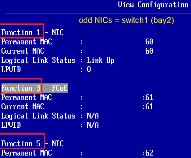
    8. The 2nd NIC should report itself as FCoE. Only 1 NIC will have FCoE functions.
      Notice that the numbering of the NICs is all even. These NICs belong to switch0 located in Bay1.
    9. Press Esc until you're back at the Emulex NIC Selection menu.
    10. Feature on Demand -> Install FCoE license
    11. You're now done with the first NIC. The 2nd NIC will have the same settings as the 1st. You will need to repeat the steps above for the 3rd NIC, and that NIC's settings will be applied to the 4th.
    12. Press Esc until you're back at the Network menu and select the 2nd NIC.
      Notice that the NICs have odd numbers. These are mapped to switch1 located in Bay2.
    13. Esc to the System Settings menu -> Emulex Configuration Utility
      If you do not see this option, Esc to UEFI main menu, save, then exit to reboot the node.
    14. Highlight the 1st NIC (001) but don't click on it. Write down the NIC's Port Name and node name in a text file for later use. Highlight the other NICs and write their PNs.
      If you don't have an Upgrade1 license for your CN4093 switches, you won't be able to use the 3rd and 4th NICs, so you can ignore them.
    15. Click on the 1st NIC. You're now at the Emulex Adapter Configuration menu.
    16. Configure DCBX Mode: Change it to CEE -- default: CIN
    17. Later on when you're done configuring the storage and the switch, come back here and run Scan for Fiber Devices and you should see the V7000 listed (ID 2145)
      Also, scroll down and click on Display Adapter Info sub-menu and you'll see the FCoE VLAN ID, if your switch was configured properly. This is auto-discovered.
    18. Esc to the Emulex Adapter Configuration menu, and select the 2nd NIC (002) then repeat the same steps.
    19. Esc to UEFI main menu, save and reboot back to the Scan for Fiber Devices for later use.
    With those easy steps, you have completed ONE node. Repeat the same for all nodes. If you're fortunate enough to have had ordered the Flex System Manager node, then it's your lucky day! You can create a Configuration Template of the configured node, which would capture its hardware component configurations, and deploy its hardware configuration to other nodes. It's magic.

    If you intend to use the Configuration Templates, I recommend that you configure all the components (internal disk RAID setup, time, boot order, ...etc.), then create the template out of the node.

    UEFI -> System Settings menu

    Network -> Select NIC

    Click on that to get the juicy settings

    Change settings as listed. Multichan is for vNICs

    Showing the available options

    Showing the available options

    Click it!

    FCoE vNIC is always the 2nd

    FCoE requires a license. Install it.

    To the next adapter

    The 2nd NIC follows the settings of the 1st


    Emulex Configuration Utility for FCoE HBA Settings

    Select 1st NIC. Note Port Name for FC zoning

    Change settings to CEE

    After storage and switch config is done, scan fiber devices

    Configure nodes for SAN boot via FCoE

    Each canister/controller will have 1 port looking at one switch and the other port looking at the other switch, which means on each switch you'll see both controllers.

    This guide is specific to V7000 and V7000 Flex and VMware ESXi 5.1 (IBM Customized Image). For other storage types, I highly recommend you read and follow the steps in the "Storage and Network Convergence Using FCoE and iSCSI" redbook (link in references). It explains booting from SAN with FCoE and iSCSI, and has excellent tips.

    1. Configure the FCoE switches and make sure that the storage and nodes are functioning properly.
    2. Create a volume and assign it to the node that will boot from SAN. It must be the first volume assigned to the node (LUN 0/SCSI ID 0).
    3. Boot the node into UEFI -> System Settings menu -> Emulex Configuration Utility
    4. Select the 1st adapter
    5. Set Boot from SAN: Change it to Enable
    6. Validate storage connectivity and volume/LUN assignment: Navigate to Add Boot Device -> Select 1st Controller
      If you don't see the storage or LUN 0000, then you need to finish configuring the switches, assign a LUN to the node, then come back here.
      Do not select a boot device here. This is only for validation of connectivity.
    7. Configure HBA and Boot Parameters -> Boot Target Scan Method: Select Boot Path Discovered Targets
      Commit Changes.
    8. Esc to Adapter Selection menu and select the 2nd adapter, and repeat the same steps.
    9. Configuring FCoE SAN boot should be sufficient on 2 ports.
    10. Esc to System Settings menu -> Devices and I/O Ports -> Enable/Disable Onboard Devices
    11. SAS Controller: Disable to disable booting from local disks on the node. Do this even if you don't have any local disks.
    12. Esc to Devices and I/O Ports -> Device Boot Priority
    13. Drag the SAS Controller to the bottom of the list. Save/Commit.
    14. Esc to Main Menu -> Boot Manager -> Add Boot Option -> Generic Boot Option
    15. Add Hard Disk 0, 1, 2, 3
      If you configure 2 FCoE ports, you'll have 4 possible paths to boot from. By selecting 4 disks, the UEFI will configure each path into a Hard Disk, and boot from the first available one.
    16. Esc to Boot Manager -> Delete Boot Option: Delete anything that you don't need (PXE, Floppy)
    17. Esc to main menu -> Save
    18. Reboot and install OS
    Note: During adapter preparation phase in UEFI, it'll probe the FCoE ports and see which one is online, and will nominate and use one of them only.

    Steps 7 and 15 allow high flexibility and reduce configuration time for implementations that have many nodes. The typical method of implementation is defining the boot LUN and path for each node. So if you have 10 nodes, and 2 FCoE ports, you'd need to repeat those configurations 40 times! Using Boot Discovery and auto Hard Disk assignment by UEFI, you avoid this headache.

    It does add some extra time to the boot process, but it's not really important at the advantage of flexibility.

    Emulex Configuration Utility

    Adapter Selection

    Enable Boot from SAN for both adapters

    You should be able to see storage and LUNs here

    Do not add the LUNs. Just validate connectivity.

    Configure HBA and Boot Parameters

    Boot Path Discovered Targets

    Add Boot Option -> Generic Boot Option

    Add Hard Disk 0, 1, 2 and 3 for a total of 4 paths

    Devices and I/O Ports

    Enable / Disable Onboard Devices

    Disable SAS Controller


    2) Configure V7000 Storage

    If you have purchased the V7000/V7000 Flex with the FCoE daughter cards, there's no configuration for FCoE. If you bought the daughter cards at a later stage, you'll need to activate them from the canisters. This won't be covered here. Please refer to the online manual.

    If you login to the V7000's web interface, you'll see each canister's (controller) Port Numbers, for both FC and Ethernet. You'll see these numbers once the switch is configured.

    V7000 Flex canister/controller 1

    V7000 Flex canister/controller 2

    Note that the port type is FC


    3) Configure the CN4093 Switches

    As mentioned before, a minimum of 2 external Omni ports must be reserved, even if you're using a V7000 Flex inside the same chassis as the nodes.

    This switch configuration will assume default bandwidth allocations. I highly advise you to read the CN4093 redbook (link in references) for optimizations.

    I'll first write the entire switch config, then explain each section.

    Login to the switch in "iscli" mode, then type "enable" to access the enable mode. Now type "config terminal" to be able to modify.

    version "7.5.3"
    switch-type "IBM Flex System Fabric CN4093 10Gb Converged Scalable Switch"
    !
    system port EXT15-EXT16 type fc
    !
    interface port INTA1
    name "Flex System Manager node"
    no flowcontrol
    exit
    !
    interface port INTA2
    name "Power p260 node"
    no flowcontrol
    exit
    !
    interface port INTA3
    name "x240 node1"
    tagging
    no flowcontrol
    exit
    !
    interface port INTA4
    name "x240 node2"
    tagging
    no flowcontrol
    exit
    !
    interface port INTA5
    tagging
    no flowcontrol
    exit
    !
    interface port INTA6
    tagging
    no flowcontrol
    exit
    !
    interface port INTA7
    name "v7000 flex node1"
    tagging
    pvid 1002
    no flowcontrol
    exit
    !
    interface port INTA8
    name "v7000 flex node2"
    tagging
    pvid 1002
    no flowcontrol
    exit
    !
    interface port INTA9
    tagging
    no flowcontrol
    exit
    !
    interface port INTA10
    tagging
    no flowcontrol
    exit
    !
    interface port INTA11
    tagging
    no flowcontrol
    exit
    !
    interface port INTA12
    tagging
    no flowcontrol
    exit
    !
    interface port INTA13
    tagging
    no flowcontrol
    exit
    !
    interface port INTA14
    tagging
    no flowcontrol
    exit
    !
    vlan 1
    member INTA1-INTA6,INTA9-INTA14,EXT1-EXT2,EXT11-EXT16
    no member INTA7-INTA8
    !
    vlan 1002
    enable
    name "fcoe"
    member INTA3-INTA4,INTA7-INTA8,EXT15-EXT16
    fcf enable
    !
    !
    vnic enable
    vnic port INTA3 index 1
    bandwidth 25
    enable
    exit
    !
    vnic port INTA4 index 1
    bandwidth 25
    enable
    exit
    !
    vnic vnicgroup 1
    vlan 3001
    enable
    member INTA3.1
    member INTA4.1
    exit
    !
    spanning-tree stp 80 vlan 3001
    !
    spanning-tree stp 113 vlan 1002
    !
    !
    !
    !
    fcoe fips enable
    !
    fcoe fips port INTA3 fcf-mode off
    fcoe fips port INTA4 fcf-mode off
    fcoe fips port INTA7 fcf-mode on
    fcoe fips port INTA8 fcf-mode on
    fcoe fips port EXT15 fcf-mode on
    fcoe fips port EXT16 fcf-mode on
    !
    !
    cee enable
    !
    !
    fcalias v7k_node1_p1 wwn 50:00:00:00:00:04:00:76
    fcalias v7k_node2_p1 wwn 50:00:00:00:00:04:00:77
    fcalias node3 wwn 10:00:00:00:00:00:00:5d
    fcalias node4 wwn 10:00:00:00:00:00:00:6b
    !
    zone name v7k_node3
            member fcalias v7k_node1_p1
            member fcalias v7k_node2_p1
            member fcalias node3
    zone name v7k_cluster
            member fcalias v7k_node1_p1
            member fcalias v7k_node2_p1
    zone name v7k_node4
            member fcalias node4
            member fcalias v7k_node2_p1
            member fcalias v7k_node1_p1
    zoneset name ActiveConfig
    member v7k_node3
    member v7k_cluster
    member v7k_node4
    zoneset activate name ActiveConfig
    !
    no ip routing
    !
    !
    end

    Configuration Explanation

    system port EXT15-EXT16 type fc
    This changes the type of the Omni ports from being Ethernet ports to FC ports. This is required to bind the ports to a storage system, whether the storage is internal to the chassis or external. If your storage is external, these are the ports where you have to plug the FC SFPs and cables to your external SAN fabric.

    interface port INTA1-INTA14
    name "port name"
    no flowcontrol
    tagging
    pvid 1002
    interface port : defines which ports you want to work on. You can specify 1 port or a range. If you have Upgrade1 license, you can also define INTA1-INTB14 to modify all 28 ports in one shot.

    name "port name" : It's better that you do this on a per port basis, to give each port a unique name, to know which system is using that port.

    no flowcontrol : Disables traffic flowcontrol. A requirement for FCoE.

    tagging : Enable VLAN tagging on a port, allowing that port to belong to multiple VLANs. Do not enable this on ports that will not use FCoE, nor require VLAN tagging. An example to this is a standalone Windows/Linux node.

    pvid 1002 : Set the Private VLAN ID (native VLAN) on the port. The default is 1 in all networks. This has to be changed to the VLAN of the FCoE on the V7000 Flex ports. If you do not have a chassis storage, no internal port needs this PVID set.

    vlan 1
    member INTA1-INTA6,INTA9-INTA14,EXT1-EXT2,EXT11-EXT16
    no member INTA7-INTA8
    !
    vlan 1002
    enable
    name "fcoe"
    member INTA3-INTA4,INTA7-INTA8,EXT15-EXT16
    fcf enable
    !
    These are VLAN definitions, and which ports belong to the VLAN and which don't.
    1002 is the preferred VLAN ID for FCoE. You can change this to whatever you want, but make sure the customer network doesn't have the same ID on the Ethernet network to not cause confusion for your nodes.

    fcf enable : Enable Fiber Channel Forwarding on this VLAN. This is a must on the FCoE VLANs if you have a V7000 Flex or an upstream (Top of Rack) switch that understands FCoE. If you're connecting the chassis to a SAN fabric, you need to enable NPV mode. See the CN4093 redbook for details.

    vnic enable
    vnic port INTA3 index 1
    bandwidth 25
    enable
    exit
    vnic enable : This is only needed if you need vNICs and want to enable it.

    vnic port index 1 : This is vNIC1 of the internal physical port 3. In other words, it's INTA3.1.
    You only need to set this, if you want to use this specific vNIC. If you do not set these settings, it'll appear as disconnected on the OS.

    bandwidth 25 : Allocate 25% of the 10Gb bandwidth, which is 2.5 Gbps to this vNIC.

    Note: You do not allocate bandwidth nor define a vNIC index for the FCoE port.

    vnic vnicgroup 1
    vlan 3001
    enable
    member INTA3.1
    member INTA4.1
    exit
    vnic vnicgroup : Create a vNIC Group to add members to it. This is a must for vNIC configurations. Not required for non-vNIC setup.
    The group members can be vNICs, internal physical ports, and external ports. In the example above, only internal ports were added. No external ports were configured.

    vlan 3001 : Each vNIC Group requires its own VLAN, and this must not be an existing VLAN. This is only for internal communication, and will not conflict with the customer side VLANs.

    vNICs not added to a vNIC Group, will appear as disconnected.

    spanning-tree stp 80 vlan 3001
    If spanning tree is enabled, this will place the VLAN 3001 in its own Spanning Tree Group number 80. The firmware will by default assign each VLAN into its own STG without having to do this manually.

    fcoe fips enable
    !
    fcoe fips port INTA3 fcf-mode off
    fcoe fips port INTA4 fcf-mode off
    fcoe fips port INTA7 fcf-mode on
    fcoe fips port INTA8 fcf-mode on
    fcoe fips port EXT15 fcf-mode on
    fcoe fips port EXT16 fcf-mode on
    !
    cee enable

    Enable fcoe initialization protocol snooping, which will detect which ports support FCoE and which don't.

    fcf-mode off/on/auto : It should be OFF for the internal ports of the compute nodes, and on for the storage and FC ports. You can also avoid messing things, and set this to auto on all ports.

    cee enable : Enable Converged Enhanced Ethernet to allow FC packet encapsulation over Ethernet.

    fcalias
    Define an alias to make it easy to identify nodes and storage ports.

    no fcalias wwn
    To remove an already configured fcalias.

    zone name
    Create a zone and add aliases to this zone.

    zoneset name
    zoneset activate name
    Create a zoneset, which is a group of zones to enable this set for the entire switch.

    no ip routing
    Disable Layer3 routing, and make the switch a Layer2 switch only.

    show fcoe database
    -----------------------------------------------------------------------
     VLAN  FCID                  WWN                     MAC         Port
    -----------------------------------------------------------------------
     1002  011000     50:00:00:00:00:04:00:77      0e:fc:00:01:10:00   INTA8
     1002  011100     50:00:00:00:00:04:00:76      0e:fc:00:01:11:00   INTA7
     1002  011101     10:00:00:00:00:00:00:5d      0e:fc:00:01:11:01   INTA3

     Total number of entries = 3

    -----------------------------------------------------------------------
    Displays the currently established FCoE connections on the switch. It doesn't show any node-storage associations. It shows the nodes/storage that has been detected to have FCoE. The section in orange is a sample output.

    show zone
    List the configured zones on the switch.

    For details and explanations of each command, or extra details, do read the CN4093 redbook (linked below in the references).

    Note: The above configuration should be the same for the 2nd CN4093 switch, except for the FCalias parts as the WWPNs will be different.

    References

    1. IBM V7000 Storage
      1. IBM Storwize V7000 Information Center
      2. Configuration Limits and Restrictions for IBM Storwize V7000
      3. Implementing the IBM Storwize V7000 V6.3
      4. IBM Flex System V7000 Storage Node Introduction and Implementation Guide
    2. Internet Small Computer Systems Interface (iSCSI)
      1. iSCSI Standard by IETF
      2. Comparing Performance Between iSCSI, FCoE and FC
    3. FCoE
      1. Storage and Network Convergence Using FCoE and iSCSI (redbook)
      2. FCoE Between Datacenters
      3. Fixing Stupid, an FCoE Response
      4. FCoE: Additional Considerations (T11 Fiber Channel Committee)
      5. FCoE Questions and Answers (Cisco)
      6. Datacenter Bridging Exchange (DCBX)
    4. Fiber Channel
      1. Fiber Channel Generations (16 Gbps FC)
      2. FC vs iSCSI (Trusted Network Solutions)
      3. FC Frames
    5. IBM CN4093 and EN4093R
      1. Application Guide for EN4093 and EN4093R - Second Edition
      2. Application Guide for CN4093 - First Edition
      3. IBM Networking OS 7.5 Release Notes for CN4093
    6. Emulex
      1. Emulex Universal Multichannel Reference Guide (Guide for the CN4054 VFA)
      2. White papers and documents for cards by Emulex made for IBM
      3. More white papers
      4. Emulex Virtual Fabric Adapter drivers, firmware and user guide
    7. Network Frames
      1. IPv6 Packets
      2. FCoE Frames
      3. Jumbo Frames
      4. Ethernet Frames
      5. Internet Protocol (IP)